The Iron Butterfly: a differential Mosfet amp with transformer input/output.
Weary of complicated projects? Here's an unbelievably simple, differential, source follower amplifier with step-up transformers loading the input/output. Producing (with 2 volts RMS input) 40 watts RMS output at 500 hz, its sound is sweet, warm, and extremely tube like. To my amazement, it's mid-range tone/sweetness crushes that of any other solid state amplifier I've fabricated.
The problem I have with most solid state amplifiers is the lack of attack on the notes. Recorded music doesn't sound live to me when played through a standard run-of-the-mill sand amp. The amp presented on this page attacks the notes like crazy--drums have punch that will make you sit up and take notice, guitar licks have a kick ass quality and any sax you come across keeps the smiles and grins in ample supply. At the moment, I'm listening to Molly Hatchet's Flirtin' with Disaster, and the only way to describe the sound is that it gets traction! I'm not rambling about a smoke screen of burning rubber, I'm talking more about grabbing a mean second gear and launching so hard the wheels come off the ground. ;^) (a few of us have been there, done that!)
The problem I have with most solid state amplifiers is the lack of attack on the notes. Recorded music doesn't sound live to me when played through a standard run-of-the-mill sand amp. The amp presented on this page attacks the notes like crazy--drums have punch that will make you sit up and take notice, guitar licks have a kick ass quality and any sax you come across keeps the smiles and grins in ample supply. At the moment, I'm listening to Molly Hatchet's Flirtin' with Disaster, and the only way to describe the sound is that it gets traction! I'm not rambling about a smoke screen of burning rubber, I'm talking more about grabbing a mean second gear and launching so hard the wheels come off the ground. ;^) (a few of us have been there, done that!)
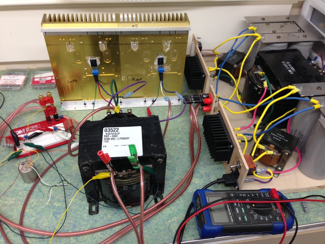
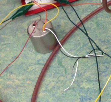
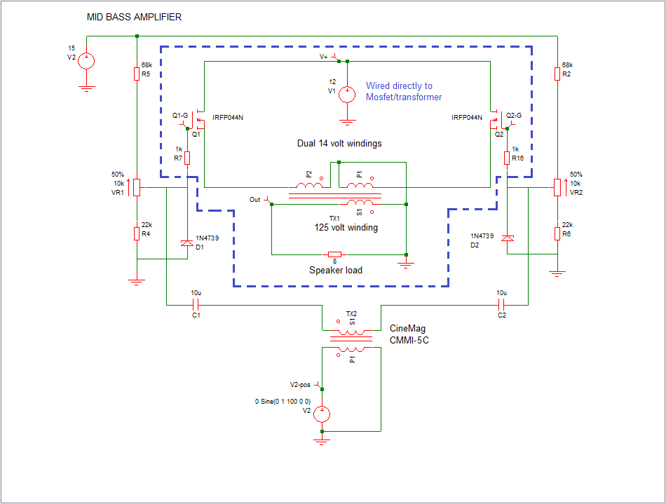
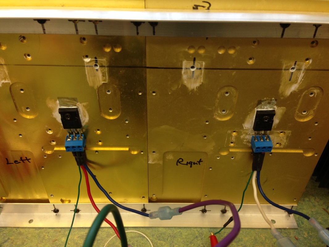
Susan Parker gets the credit for inspiring me to design this super simple little project, a project that began with the need for a mid bass amplifier for my 100 hz horns. What you're looking at in the picture, above, are a pair of IRFP044N mosfets coupled to the secondaries of that 35 lb, big, black beast of a power transformer in the middle left of the page. The transformer's dual secondaries are rated at 14 volts, the primary is 125 volts. You can observe the connection sequence in the schematics, below.
Here's the prototype amp under construction--that's 10 gauge ground/speaker/power wire. Upper right hand corner: I'm using a 15 volt DC power supply I happened to have lying around for the bias voltage. Sitting on the transformers is the bias circuit board for both channels. The amp is fed 110v AC and 12v DC from the separate power supply (above right). So far, the amp weighs in somewhere around 100 lbs. and the power supply weighs about 50 lbs.
Here's the prototype amp under construction--that's 10 gauge ground/speaker/power wire. Upper right hand corner: I'm using a 15 volt DC power supply I happened to have lying around for the bias voltage. Sitting on the transformers is the bias circuit board for both channels. The amp is fed 110v AC and 12v DC from the separate power supply (above right). So far, the amp weighs in somewhere around 100 lbs. and the power supply weighs about 50 lbs.
Step-up transformer amplifier (the movie)
Why should Hollywood have all the fun? ;^) Here's a one minute clip of me doing my best to make you dizzy.
The Circuit:
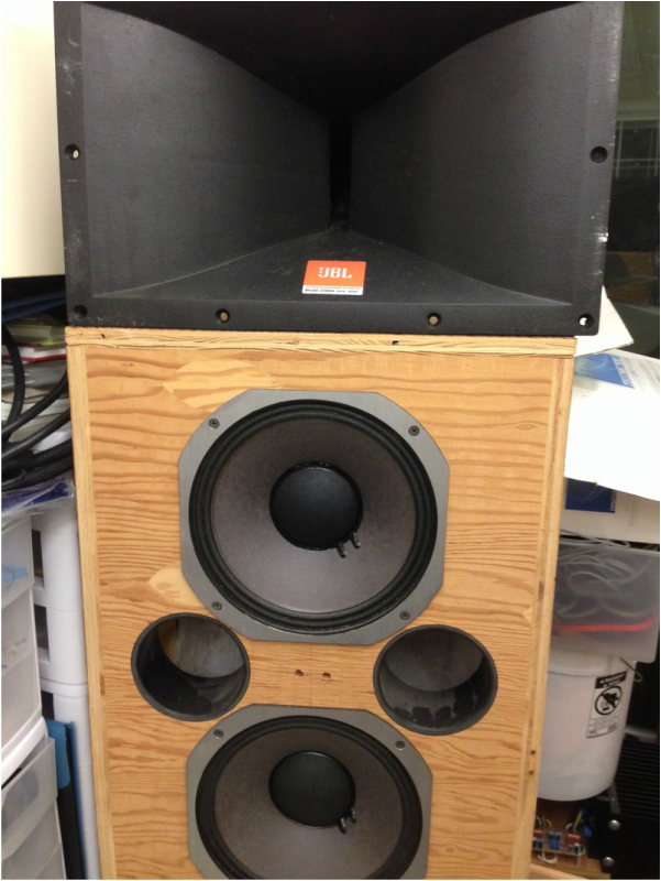
From the schematics you can see the secondaries are center tapped with the tap going to ground. You'll also notice that there are no power resistors in the mix--not a one--I figure that if I'm careful, the transformer has enough resistance to protect the transistor. Honestly, the sound is just too good to be true. Being a mid bass amp, I don't require broad bandwidth, and didn't expect much with a power transformer that has no interleaving between primaries and secondaries, but the frequency runs well above 6000 hz (in fact, the scope displayed a respectable, though significantly smaller, 4 volt output sine at 20k). Sitting here in my lab, I'm currently listening to a paralleled pair of JBL 2123 drivers (with a series connected 0.18 mH choke) in a ported 100 hz bass reflex enclosure with a JBL 2446 compression driver (sporting a 2 uF cap) coupled to a 2380A horn. My receiver is set to cut frequency response below 100hz, so the 2123s are protected from heavy bass transients. I have a powered subwoofer pulling up the first couple of octaves.
In this configuration, I'm operating the mosfets with a V+ of 12 volts--no V- is required. The heat sink is slightly warm. The VGS is currently set to 3.7 volts, so the FETs are just barely turned on, and I assume this amp slips into class A/B rather quickly. I've noticed that with low VGS, the amp sounds decent with this transformer. I appreciate the cooler heat sinks too. The efficiency must be fantastic.
The input signal is fed through a CineMag CMMI-5C transformer which has a 5 to 1 step up. Being a follower amp, all the gain is produced by the input and output transformers (not the transistors, their job is to modulate the current). Stunning concept, if you ask me.
On the right side of the top picture you see the dual mono power supplies (I'm only using one at the moment). They're an LC configured affair, and do a decent job of providing plenty of current. Notice that I'm using the same 1600 V/A transformer. What's cool about this arrangement is that I purchased a small pallet load of these transformers and now I have a way to put them to use. :^)
My original idea was to fabricate a simple, transformer loaded, mid bass amp that had a direct, clear sound, and didn't require feedback. Turn on/off thump had to be avoided, as well. I feel that has been achieved. From my recently acquired tube audio experience, I've come to realize that part of the charm of tube devices is the output transformer. I like the warmth and springy liveliness you get with this arrangement, thus the concept of a stronger, more affordable mosfet/transformer, mid bass amplifier came to mind. Power mosfets are quite common/reasonably priced (a buck apiece compared to $30.00 for an entry level KT-88 power tube), have a silky sonic signature when biased properly, and will fill the bottom end of my sound system quite nicely. I used the IRFP044N transistor because it prefers to pass a lot of current, and does so with low VGS. Part of getting a good sound out of an amplifier is placing the transistor in an environment where voltage and current properly align. Since this amplifier has no power resistors, and the transformer's dual secondaries have extremely low DC impedance (the resistance is so low that it can't be measured with my meter), it's a sure bet that this amp is going to pass a lot of current. Hence, the need for the IRFP044N's ability to pass current like it's going out of style.
Note: in retrospect, and after much experimentation, I've noticed that the IRFP044N passes too much current and requires a power resistor at the center tap of the output step-up transformer. Should anyone proceed with this project, keep this in mind. I've had better luck with the IRFP240 with regards to current regulation.
Improvements:
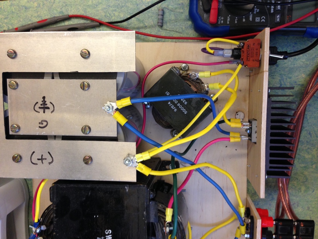
First comes the power supply--I wanted to experiment with a bifilar wound choke for the LC filter (the first picture at the top of the page depicts an LC power supply that employs a standard choke). Call me crazy, but my thought was that the common mode rejection factor would improve, the choke resistance would lower, and best of all, I'd find a way to utilize the surplus chokes I'd ordered for my Choke Loaded Class A Amplifier.
Well, first of all, the concept works beautifully! The hum from the 4 ohm load (2 eight ohm drivers in parallel) decreased to almost nothing. With the original LC power supply I heard a slight hum, after this application it's gone.
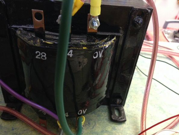
What I didn't expect was that the LC circuit would behave as if the choke were not in the path (although the hum had vanished due to the choke), i.e., the voltage from my 14 volt lug of the power transformer wasn't the previous 12 volts, but held at nearly 19 volts. You could have knocked me over with a feather! Below is a picture of the power supply and it's wiring.
Well, first of all, the concept works beautifully! The hum from the 4 ohm load (2 eight ohm drivers in parallel) decreased to almost nothing. With the original LC power supply I heard a slight hum, after this application it's gone.
What I didn't expect was that the LC circuit would behave as if the choke were not in the path (although the hum had vanished due to the choke), i.e., the voltage from my 14 volt lug of the power transformer wasn't the previous 12 volts, but held at nearly 19 volts. You could have knocked me over with a feather! Below is a picture of the power supply and it's wiring.
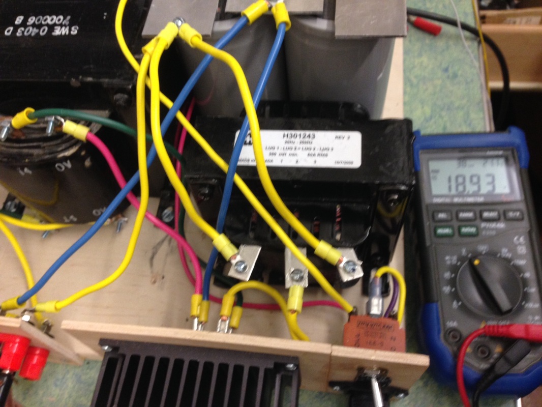
You can see the green wire connected to the 14v tap on the power transformer. It and the pink wire connect to the bridge rectifier. From there, the rectifier's positive output is connected to the center tap of the bifilar wound choke via the yellow wire. The outer lugs of the choke (1&3) connect to the positive post of the capacitor bank via a pair of 10 gauge, yellow wires. It's so simple it's scary, just like this amp. I keep checking the speakers (with the source material on pause) to hear any hum or static. It's dead quiet.
Moving on:
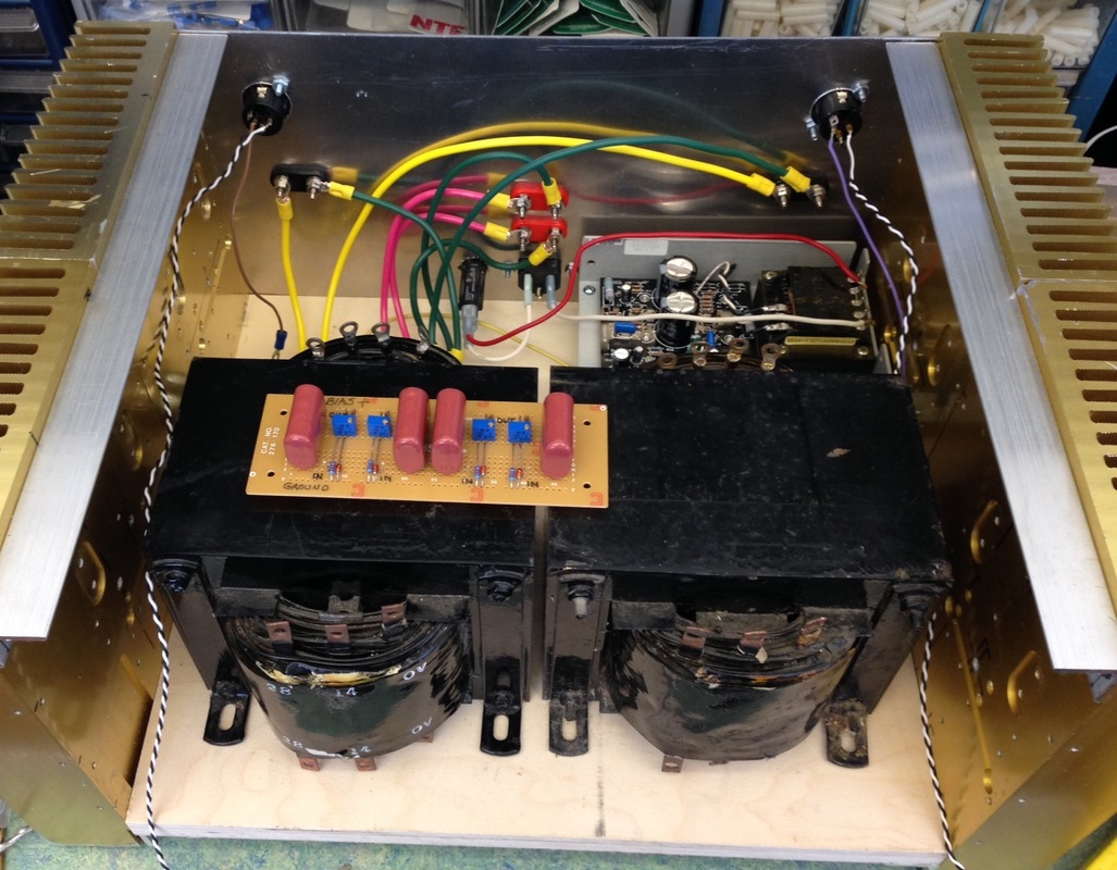
I modified the original circuit (no longer shown to avoid confusion) in an effort to gain complete control of the mosfet's bias voltage (notice, in particular, the dedicated 15v bias voltage supply). This is a sensational idea in that fluctuations in the primary power supply won't cause VGS oscillation and runaway behavior. This amp draws plenty of current, and all, even minor adjustments to VGS bias dramatically alters the primary power supply voltage/current draw which, in turn, affects gate voltage and the resulting current flow through the transistor. Several times, when I originally drew transistor bias power from the primary power supply, I've heard a buzz, and then a POP--the end result being a pair of blown mosfets. That kind of takes the fun out of the experiment.
Note: To protect the mosfets, there are a pair of 9.1 volt zener diodes connecting R7 and R16 to ground.
In my test model, R5/2 are 100k, not 68k as shown in the sim. 68k resistors will increase the VGS and the power draw. Initially, I'm proceeding with caution by using the 100k devices. For the moment, I've set the VGS bias voltage to 3.4 volts.
Adjustment: OK, I just replaced R5/2 with the 68k resistors and adjusted the VGS bias to 4 volts. The sine looks stronger, rounder too vs. saw-tooth. The transistors are receiving 7 volts at the drains and get hotter far more rapidly with 4 volts VGS bias.
Adjustment: I lowered the VGS bias to 3.7 volts and noticed the variac's power supply voltage jumped from 7 volts to 8.3 volts. The sound isn't quite as rich, but the mosfets are running considerably cooler.
Adjustment: I brought the power supply voltage up to 12 volts and can hear that lushness returning to the mix. Transistors are running barely warm. (Note: Though the heat sink is cool, when the transistor hold down screw heats to the point of discomfort when touched, there's too much current running through the transistor).
Adjustment: I brought the VGS up to 3.75 volts and notice a smoother sound. The heatsinks are warm, not hot, and I can hold my hand on it indefinitely.
I've noticed (on the scope) that altering the primary power supply voltage has zero effect on the sine wave output (at least with the amplitude of the signal I'm using. A higher voltage output may change everything). I can run the primary voltage from 3 volts to 12 and the sine remains the same. I'm testing through a power resistor (instead of a speaker), so can't describe the sonic signature. Increasing the VGS does increase voltage output, so I'll be exploring this feature and will comment as information is collected. (I have, subsequently, listened to 6 volts vs. 12 and notice that higher voltages yield a better sonic signature)
Finally: After modifying my power supply with the bifilar wound choke, and sending the amp 19 volts instead of 12 (as mentioned above), I blew the IRFP044N transistors. Fact of the matter, they overheated. One actually caught fire--never had that happen before. Fortunately, nothing other than the pair of power mosfets were damaged. After some thought, I considered the fact that the 044Ns like to pass a lot of current, and perhaps I would have to give the IRFP240 a try (they pass roughly 1/10 the current with similar VGS). I connected a matched pair and have been listening for almost a half hour with no mishaps. I'm keeping the gate voltage at 4.6 volts, and the measured VGS is 4.25 volts. This turns the transistor on, but not hard enough to kill it with current. It's a good sounding transistor too.
12/27/2014: I received a lovely email from Susan Parker, the originator of this amplifier concept, and she mentioned an idea to prevent parasitic oscillation with the use of ferrite beads at the mosfet's source (I assume you'd use a bead around the gate pin, but she may have meant the source pin because it's connected to the step-up transformer). I requested more information from her on the subject, and will post the results of my query as they arrive. Wouldn't you just love to be her neighbor! :^)
I did a quick leap through Google's search machine and gathered some ideas of what the ferrite beads can do for this project. Simply slipping them around the gate of a mosfet will suppress high frequency radiation and the effects it causes in the transistor. If one were to add them to the source pin, I imagine that any radiation/ringing being projected from the step-up transformer will be suppressed as well.... hummmm.
5/21/2015: It has been awhile, but I'm running the amp though its paces in the lab. First thing I noticed is the sine wave wobbling around on the scope... the 8 ohm resistor load is getting quite warm too. For some reason, as I peered through the Cinemag schematics, I noticed the unused black and white grounding wires (you can see them in the photo, below). I connected the white wire to ground--nothing changed on the scope. OK, how about the black wire. Presto! the wobble in the sine wave has diminished appreciably. The resistor has cooled down, and remains cool.
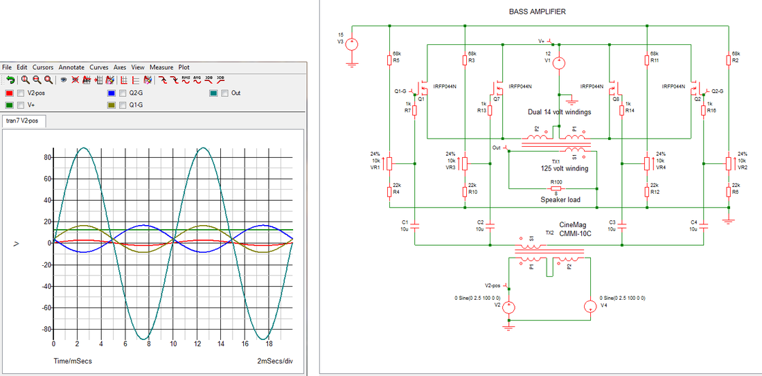
(The schematic below is the basic amplifier--click to enlarge)
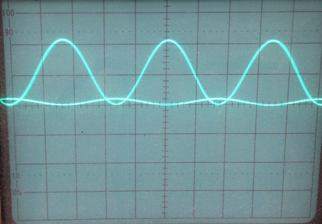
Here's the scope pic at 500hz. Notice that 1v input (peak, not RMS) yields about 10.75v output.
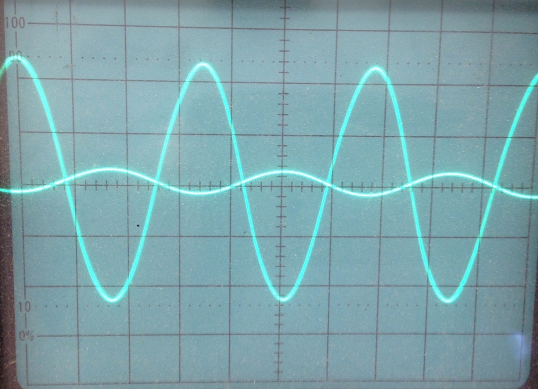
Below, full volume: 2 volts RMS input yields 17.7 volts RMS output (measured by my voltmeter) and the resulting image on the scope. No clipping, yet. What's really cool: in this picture, I was only using a 12v power supply.
If you want to get serious voltage gain, build a tube hybrid:
This is a super simple arrangement that uses a single ended driver tube with a high Henry plate/anode transformer. The output of the transformer feeds the inputs of the mosfet differential stage. It's about as simple as playing checkers and sounds fantastic. The speakers in this video are JBL 2123 pair running in parallel. There's no woofer, no tweeter, and the JBL 2123 is a midrange/upper midbass driver. Overall, I'm quite impressed with this application.
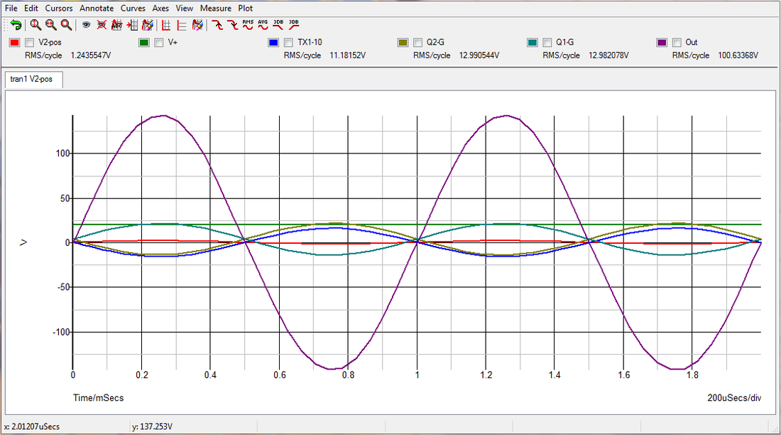
600 watt simulation:
The circuit below is a sim, and has not been tested. I'll display the necessary changes after I build the beast. What's interesting is the extreme voltage/power gain with a mere 12 volt power supply. It seems impossible to achieve performance of this magnitude, and time will tell. Since there's no power resisters in this design, I gave every mosfet its own bias circuit. Perhaps by adjusting/maintaining matching VGS on each device, current hogging can be prevented along with the potential damage.
Some thoughts:
1. The input step-up transformer is delivering just shy of 17 volts--good thing too, the gates wouldn't handle more than 20 volts.
2. There will be more mosfets than depicted in the schematic. Heat sinking will be larger than that of the test model.
(click to enlarge)
Some thoughts:
1. The input step-up transformer is delivering just shy of 17 volts--good thing too, the gates wouldn't handle more than 20 volts.
2. There will be more mosfets than depicted in the schematic. Heat sinking will be larger than that of the test model.
(click to enlarge)
1500 watt simulation:
Yes, there's more to be had from this amplifier--at least in the virtual world of simulating software. Here's a hefty beast that would have to be a monoblock and would have rather impressive looks. The primary voltage has to be bumped up to 20v, and the bias voltage would have to be lowered to compensate. I'm looking forward to experimenting with this design. (click to enlarge)

Parting shots:
Several resistors, a couple of caps and potentiometers are all that's required for the basic amp pcb module. This arrangement is used simply to bias the transistors. Being a Source follower transistor configuration (with no gain from the mosfets), the input/output transformers create the gain.
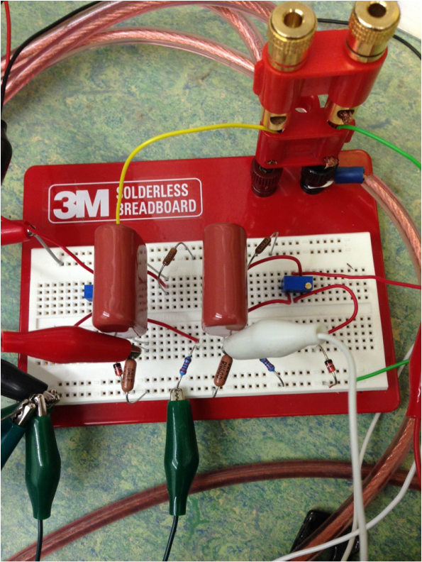
Below, you see the input transformer (as mentioned above, run the black wire to ground to mitigate oscillating):
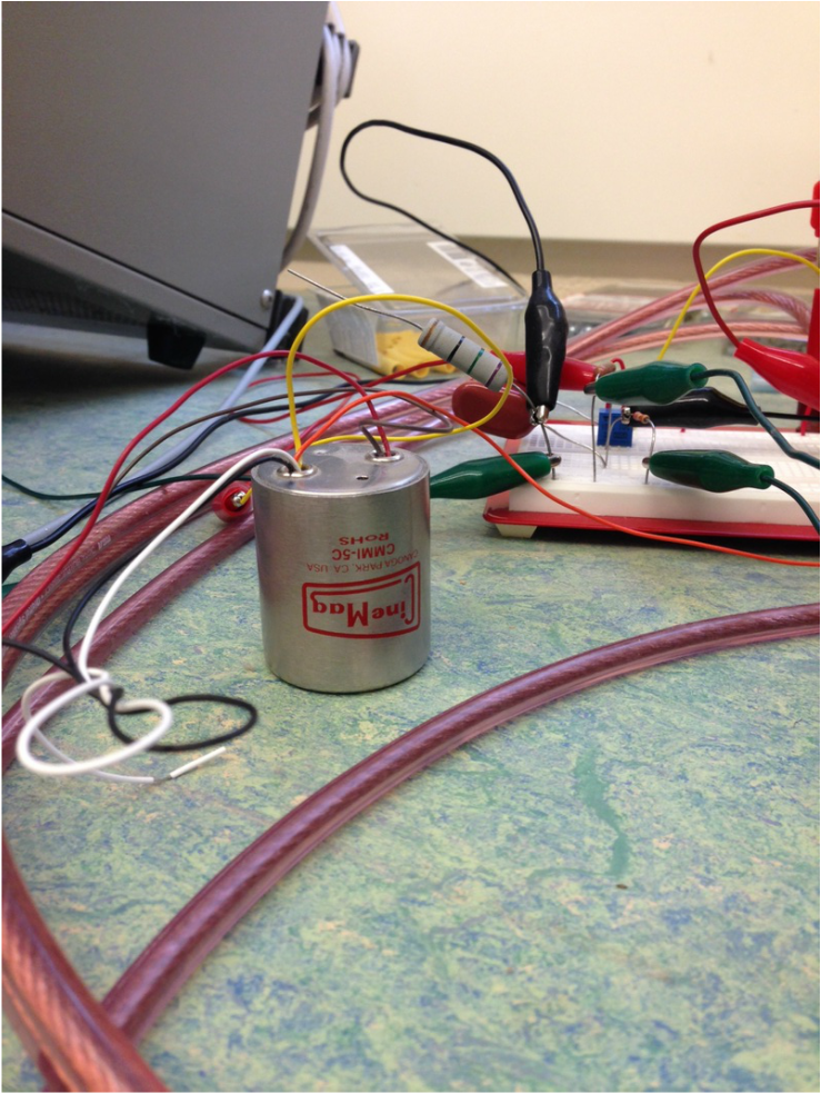
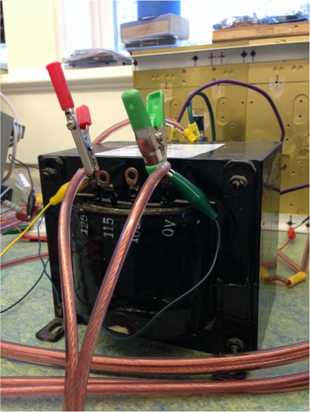
Though difficult to observe, the vertical green wire connects the center tap: 14V to 0V. The purple wires are also 14V and 0V; one is on the lower left 14V lug, the other is the upper right 0V lug.
The original LC power supply is shown below. I heard a slight hum with this arrangement, so tried the bifilar wound chokes as mentioned in earlier in the text. The reduction in noise is like day and night.
My old, faithful, JBL speaker/horn combo: