DIY Class-A Amplifier
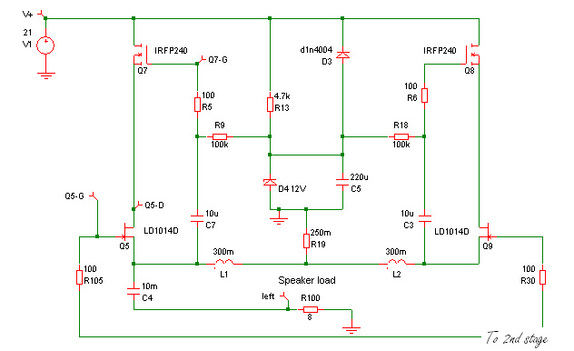
Here, I present a scalable, three stage, class-A amplifier with two differential gain stages and a differential, power buffer output stage. The third stage power buffer in this amplifier is unique in that it's Source pins are loaded with a bifilar wound choke (depicted in the second schematic down). I'm prototyping several versions of this particular design and will post results as they arrive.
In this design, I did a good job of matching transistors in the differential pairs. There are no adjustments available in the third stage, so match the IRFP240 and LU1014D transistors to within 0.01 volts in each set (the mosfets don't have to match the jfets ;^). The amp I'm listening to has a DC offset of less than 4 millivolts, which is well within reason.
I think it appropriate to mention that I learned many of the concepts displayed on this page from the legendary Nelson Pass. His Zen tutorials have been the fuel to my inspiration. Furthermore, it was Nelson who suggested I learn to use simulation software (probably because I was asking so many questions ;^) Thankfully, I followed his advise. If you're new to class-A amplifers--FET amplifiers in particular--then I recommend you journey over to Nelson's DIY pages (passdiy.com) and read his articles. You won't be disappointed!
9-18-2010: I altered the values to the IRFP240 power mosfet gate C/R--this mosfet pair is the voltage regulator for the third stage. Instead of 220uF, I inserted my favorite sounding Panasonic capacitor rated at 10uF. Doing this required that I increase the bias voltage resistor value (from the zener) to 100k. I came up with the idea as a means to explore a better sounding cap to modulate the voltage regulator gate, and to inhance high frequency output.
The sound seems smoother when played loud. I don't totally trust my ears/mind (I know how easy it is to form a mental bias regarding circuit alterations), but besides being less shrill when played loud, it also seems to offer deeper bass with more punch.
9-19-2010: I increased the zener value from 9.1v to 12v. This zener controls the gate of the IRFP240 voltage regulator. I also increased the power resistor value from 0.250 ohms to 0.5 ohms. Sound is very sweet, and I notice more usable (translation: low distortion) power than before.
10-7-2010: I increased the value of the first stage drain resistors (R15 and R17) from 220 ohms to 612 ohms. It's an odd number, but came about by soldering 392 ohm resistors in series with 220 ohm resistors.
The idea to adjust these values (R15 and R17) came to me when reading one of Nelson Pass' articles (the tutorial section of the F5 owner's manual). In my amp's original configuration, the second stage mosfets had just enough gate/source voltage (1.3v) to turn the device on. After reading the F5 manual I notice that Nelson uses 3.6 volts. A light bulb in my head literally exploded and I found myself simming the idea of increasing the gate/source voltage in my amplifier. I liked what I saw in the sim and performed some voltage readings on the amp. The 1.3v gate/source voltage value matched the sim. Naturally, I soldered in the pair of 392 ohm resisters in series with the existing 220s and turned the thing on. The gate/source voltage on the second stage mosfets is now 3.65 volts.
The results are extremely positive. The amp sounds smoother that ever! Distortion is very low, at least by my ear's evaluation. There's also more snap in the music--transients are startling.
Where would we be without Nelson?
10-12-2011: Almost a year later, wow. I'm toying around with an all mosfet 3rd stage. I have submitted a schematic and a description in this post, just above "PCB Art". This modification is potent and allows me to design power amps that are capable of driving Pro Audio horn arrays. Imagine a clean sounding PA.... shivers...
12-27-2012: Time waits for no man, or so they say. With that being said, I noticed that it's been a while since I posted my adventures with this amp, so I thought I'd mention a few developments. First off, the mosfet 3rd stage is a wonderful success, and I can't see any reason to fret about the lack of LU1014D power jfets.
I've switched to water cooling and love it, I mean, it's so compact and reduces the weight of this beast by half! Aluminum may be lighter than most metals, but when there's enough of the stuff, it breaks a man's (or woman's) back moving the amp from location to location. You can read about my water cooling adventures on my DIY Water Cooled Amp page. It's easy to do and works quite well.
I've also been exploring air core inductors vs. iron core. Iron is great when you want a lot of inductance in a small package, not to mention lower resistance--iron inductors use less wire which means less resistance. That's the problem with air core inductors: they increase the resistance at a critical juncture in the circuit. The iron core units I use (from Hammond Transformers) have 0.018 ohm resistance, which is unbelievably low, but the air core devices are 1.7 ohms. To make matters worse, the inductance falls from 300 mH to 25 mH. This is the primary reason why I've put off using them in this amplifier.
Until now:
My high frequency, paper mache horns are extremely efficient, so I don't really need more than ten watts, or so, to get them up to concert level in my listening room, and since I listen to jazz, I only require several watts tops. Better still, I only needs the amp to operate above 450 Hz. After some simulation work with Simetrix, I discovered that this is achievable with air core inductors. The only modification required to the circuit would be to increase the power supply voltage from 24.5 volt to 29.5, and swap out the chokes.
I moved an AC input lead on the power transformer and voila, 29.5 volts. That was simple. Replacing the chokes shouldn't be too difficult, just a bit of soldering, which I find relaxing. Piece of cake. My fingers began to tremble--what can I say, I love this kind of stuff!
Into my Class A, stereo amplifier, I inserted a pair of 25 mH, bifilar, air-core chokes wound with 16 gauge wire. Satisfied with the soldering job, I shut down the soldering iron, flipped the power switch on the amplifier, inserted a jazz CD (Miles Davis: Kind of Blue) into the CD player and sat back into the recliner hoping for the best.
Oh my god....
There are no words to describe how this amp sounds. I can cobble together a euphemism such as "Liquid Gold", but that sounds corny. Yet, these are the only two words that aptly describe what I heard. I listened to the entire CD as if it were my first time. Yes, the sound had changed that much. I didn't realize how much sweeter the amp could sound with such a simple change. It's a DIYers dream. Anyone can build this amp, and anyone can wind this simple bifilar choke.
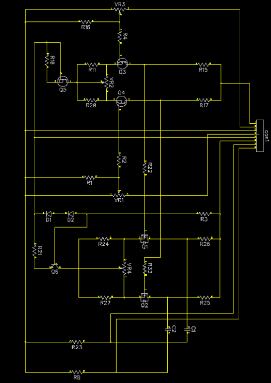
Circuit description:
In the first stage, an LSK389B dual jfet is charged with splitting the input signal (if single-ended) and boosting the gain a bit. This is a beautiful sounding transistor, hopefully one with a long production run. It's output is direct coupled to the second stage IRF630 mosfets where we pick up voltage gain--quite a bit, actually.
Moving on:
The third stage IRFP240 mosfets are serving dual roles: their gates are regulated by a 12 volt zener diode in an effort to create a simple voltage regulator. The gates are also modulated with a signal from the output (through a pair of 10uF capacitors). This serves the very useful function of moving the static voltage located at the IRFP240 mosfet source pins into a sympathetic sine that matches the sine at the power jfet's drain pins, thus allowing the jfets greater voltage swing/headroom.
In the schematics, you'll notice that there's no local/global feedback in the first two stages. I do use Source degeneration--a type of feedback. Source degeneration is also an excellent way to control gain.
A prior, 3 watt version has been fabricated and sold to a friend. 3 watts doesn't sound like much, but this amp has no trouble driving a pair of 10" Audio Nirvana speakers to SPL levels that get the lady-of-the-house involved with that timless: "Turn it down!"
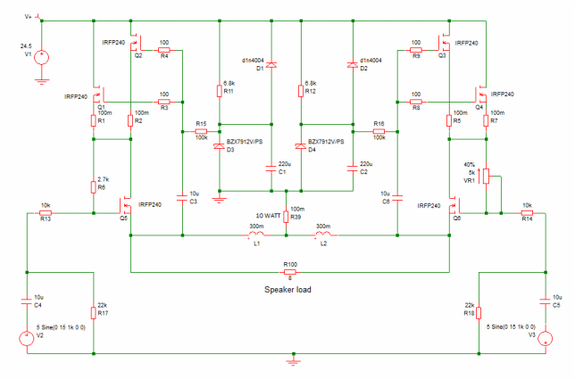
FYI: I've simmed a scaled up version of this design (45 watts). Then again, it's only a simulation. I've read from fellow DIYers that the LU1014D power jfet doesn't appreciate/cooperate with parallel units. My simulation tends to contradict that arguement, but like I said, it's only a simulation. Someday, I'll try paralleling LU1014D and see what happens.
Regardless of the output voltage, everyone seems to love the sound... Eric, the friend I sold the first prototype to, compares the sonic signature to "red wine". I think that's his way of saying the amp has a romantic sound. That makes me smile.
Signal stage schematic:
Below, are the schematics from the simulator--all three stages. Labels don't match the circuit above.
I originally had a 20 ohm resistor below the 2nd stage CCS (MJE3055T). It has been replaced with a 6.8 ohm device. The change came about this way: The VGS in the second stage Mosfets is 3.6 volts which is too low to analyze on the IRF ID/Drain-Source voltage graphs (they cut off VGS measurements at 4.5 volts). I began this adventure with a safe value of 20 ohm--with which the sim agreed--but found the sound from the amp a bit shrill, even after dialing in the 3rd stage. I decided to parallel another 20 ohm resistor with the original and give her a listen. Wow, much better! Well, would a third resistor help? I gave it a try--YES, it sounds better still. Being a bit cautious, I decided to stop there and let the amp warm up. After an hour, the heat sinks are much hotter in the second stage. 46 degrees C on the MJE3055T and 41 deg. on the IRF630 mosfets is quite acceptable. The amp sounds fantastic. The music is very smooth, relaxed, yet the drums are strong, as is the bass guitar. I'm listening on the little line-array that's displayed on my Line-Array page. What a pleasure this is becoming, just wonderful!
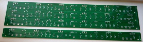
Signal stage pcb to the first schematic:

The sound coming from this arrangement more than pleases the ear, it literally made me smile at the added, almost ultra, ease of its musical presentation. Graininess has almost completely disappeared, and there's no shrill artifacts -- just liquid smooth music.
The quest for greater power output:
The sonic signature is extremely smooth and detailed. I like this sound every bit as much as the power jfet model. In fact, the additional detail is obvious with the mosfets, not to mention there's a great deal more output wattage available. The sims suggest 40 watts for this layout (up to 200 watts with additional output mosfets) which I'm inclined to believe. I'm able to generate more volume with my office speaker than my ear can tolerate -- much more than the power jfet amp.
The best part of this discovery: the amp sounds just fine without the discontinued LU1014D power jfet. I value my discovery for this reason more than any other.
PCB art:
The CCS below the first gain stage is set up to use either a j310 or a 2SK170 jfet. The 2SK170 jfet is not a drop-in replacement for the j310--it requires modified perifial component values, not those listed in the schematics.
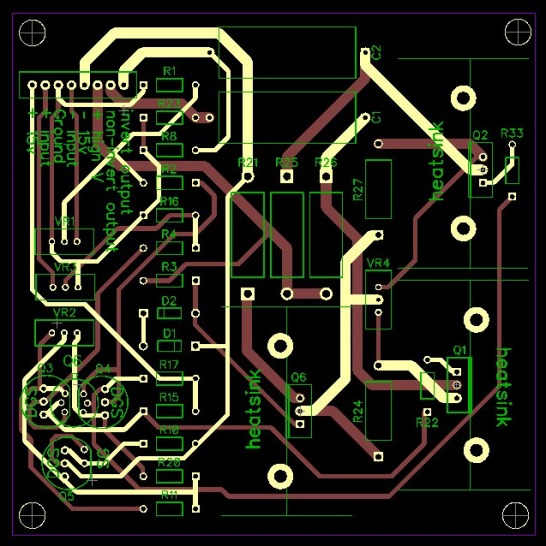
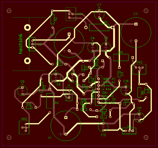
Third stage pcb:
I designed this board to allow some flexibility in output power. You can experiment with one or two pair of output power mosfets, depending on Mosfet combination/and how much wattage you want from the amp. If you want more than 10 watts, you'll be using more power devices than the pcb allows--but that's no problem, just wire up a bunch and connect their leads to the pcb. Obviously, the current-sharing resistors will be off-board--one for every power mosfet/jfet.
Thoughts regarding mosfets:
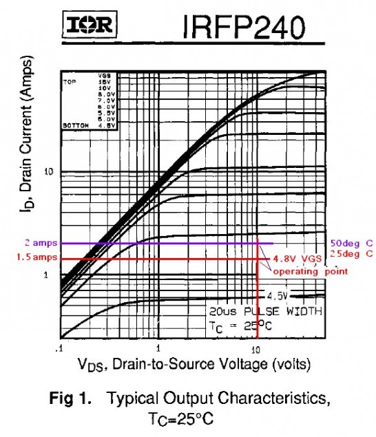
For instance, the IRFP240 transistor operates with far less amperage for a given VGS than the IRF044N. If you run double transistors, or the incorrect transistor, you'll starve them for current and the music will sound thin and strained.
Another point worth considering: heating the transistors alters their current gain characteristics. Let's say we're operating at a Drain/Source voltage of 10 volts on the third stage IRFP240, with a VGS of 4.8 volts, the mosfets prefer to pass around 1.5 amps at 25 degrees C. Operating at 175 degrees C (which we never do, but that's the other graph provided) the amperage passed more than doubles. Fortunately, we only raise the temperature to 50 degrees C. The point is this: Mosfets pass more amperage as they heat up--so keep that in mind when forecasting their amperage.
In this example, I'm just guessing that at 50 degrees C the mosfets will prefer to pass 2 amps. So for a VGS of 4.8 volts, the current passed increases as the device heats up and you may no longer remain in the sweet spot.
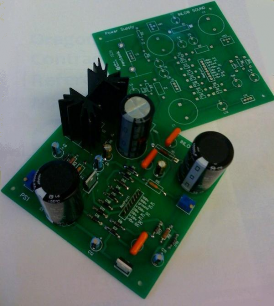
Show below, a power supply for the signal stages.
Below, I've added a picture of the actual signal stage power supply.
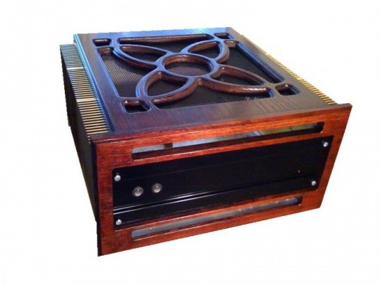
An amplifer needs a chassis. I designed and fabricated this to house the ideas presented on this page.
I discovered that I'm not the only one:
| us4096443.pdf |