Inlow Sound 15B Bass Horn
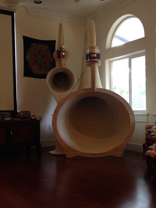
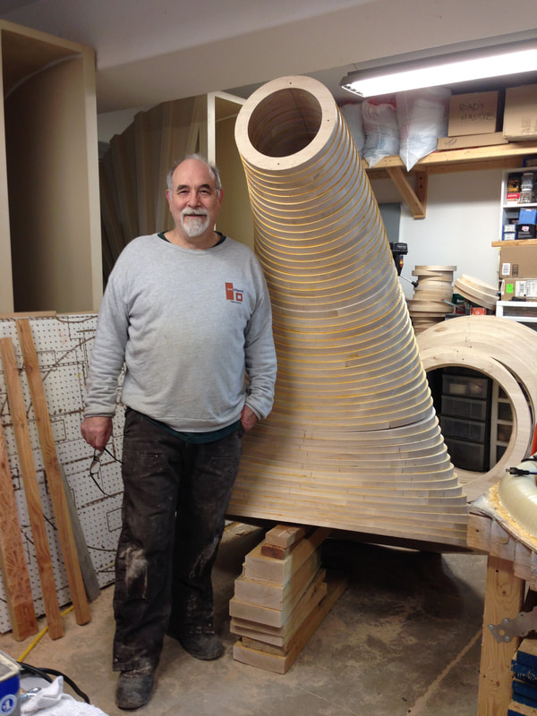
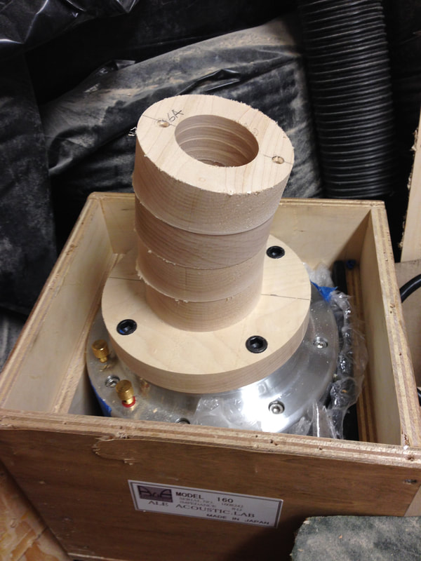
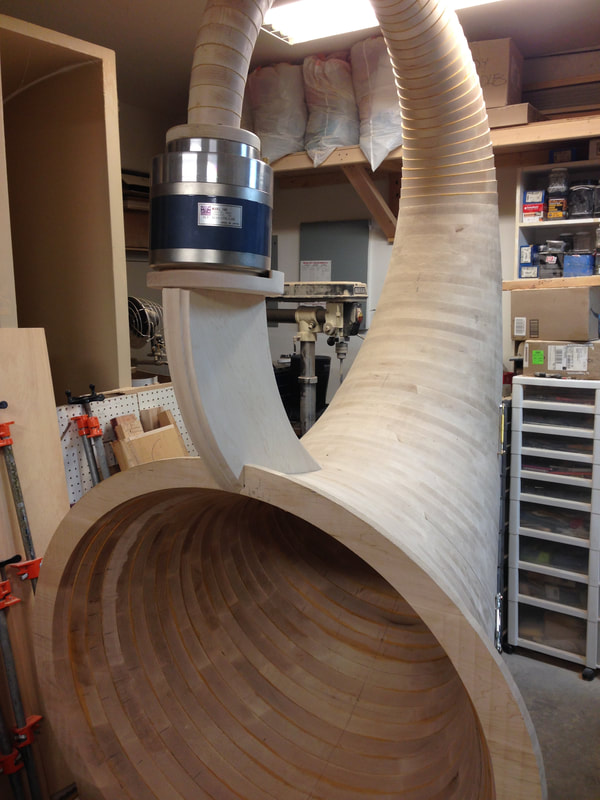
This is a monster of a bass horn. It's over eight feet in height and nearly five feet deep. Its mouth is four feet tall and five feet wide. With a proper driver, it has a range of 40 Hz to 400 Hz. The picture above depicts my 15-B being driven with an Ale 160 driver.
I'm fabricating my horn to compliment the 15-A (shown to the rear--above--and on the previous website page).
This is the first of two to be completed--that being said, I thought some of my friends and fans would appreciate pictures of the fabrication process.
I'm fabricating my horn to compliment the 15-A (shown to the rear--above--and on the previous website page).
This is the first of two to be completed--that being said, I thought some of my friends and fans would appreciate pictures of the fabrication process.
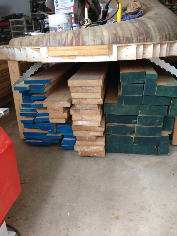
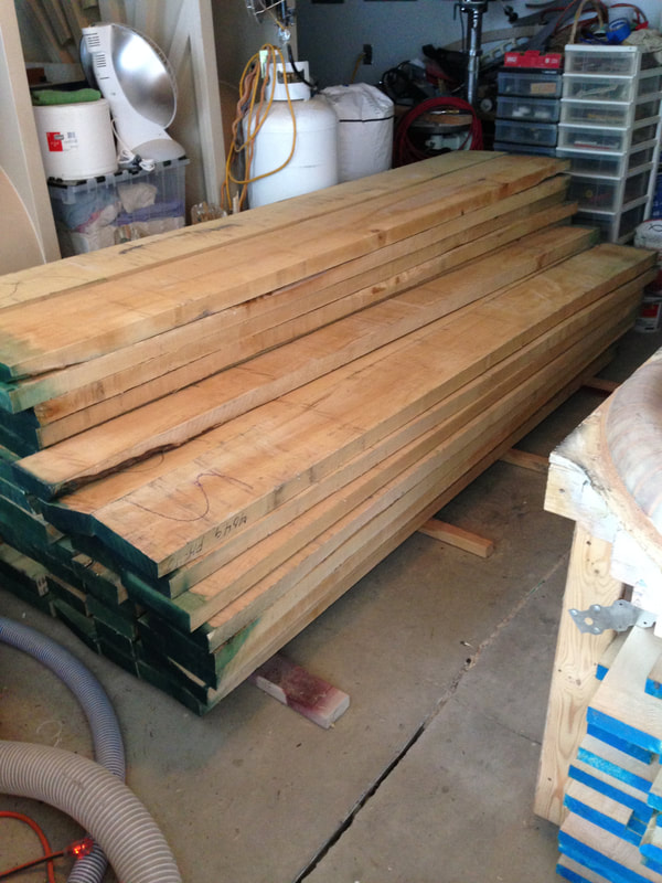
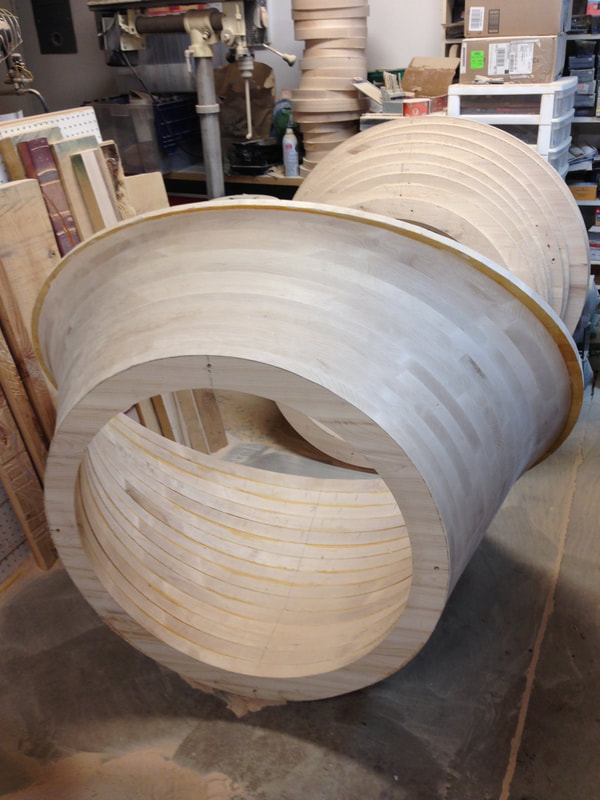
The process begins will a lot of lumber--in this case, hard maple. The mold (above the stack of lumber) is for fabricating the 15-A, the midrange counterpart.
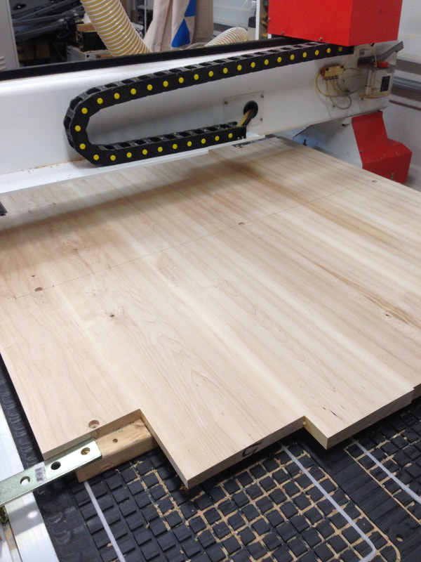
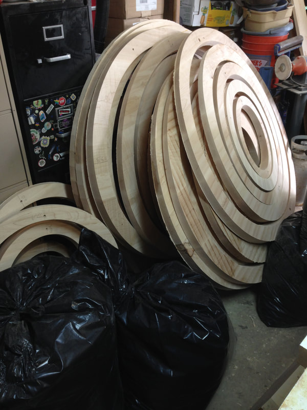
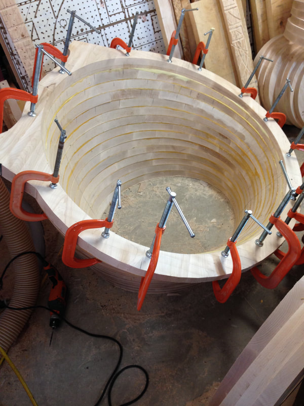
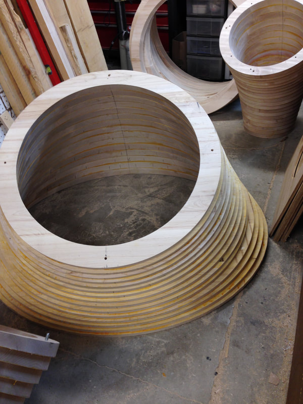
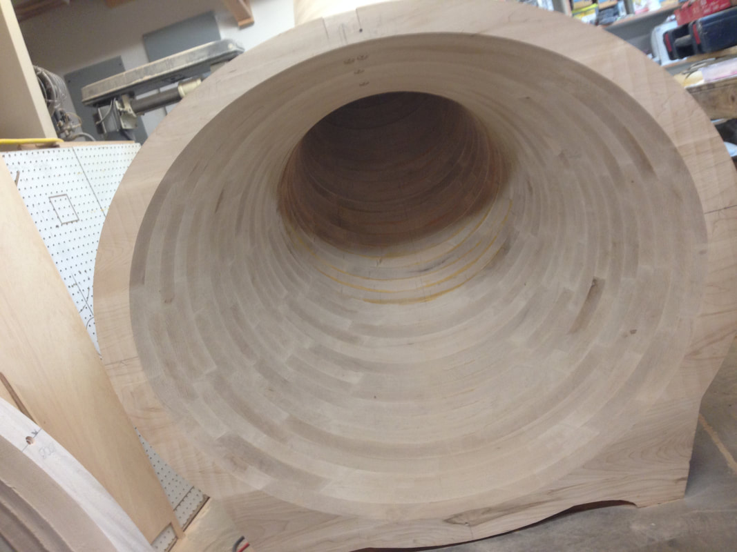
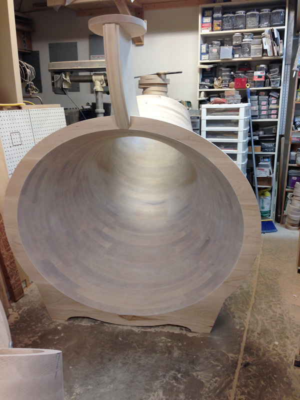
The maple is squared, planed, edged and laminated to create the building blocks that form the rings of the horn. Below, you see a pile of rings forming, and I've only scratched the surface... there's 46 rings showing, and I have a total of 208 to fabricate. Fortunately, I began with the larger rings (which take the longest to fabricate) and have increasingly smaller, and smaller rings left to machine.
Ohhh--those black contractor's bags are full of sawdust from the fabrication process. I plan to build a sawdust burning stove to heat the shop this winter. :^)
Ohhh--those black contractor's bags are full of sawdust from the fabrication process. I plan to build a sawdust burning stove to heat the shop this winter. :^)
A few more updated photos:
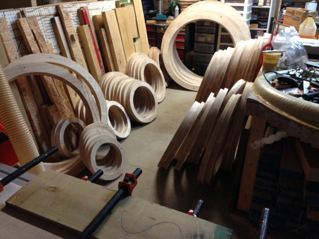
Above: I'm sorting the rings numerically.
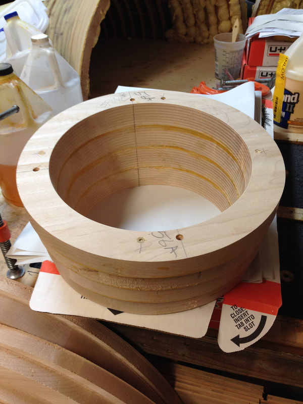
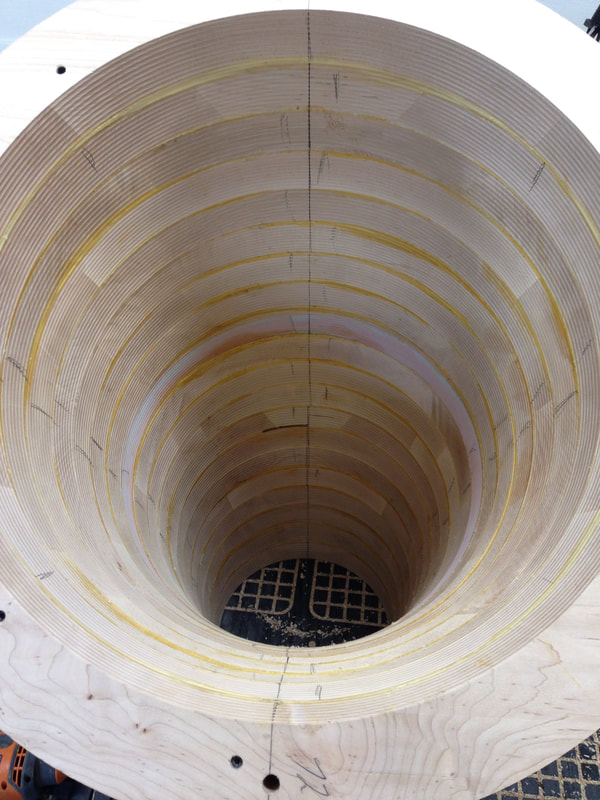
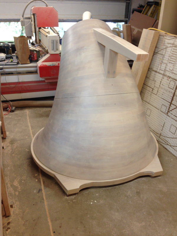
There are a few hick-ups to be ironed out, but the assembly is coming along quite well. I have the 180º goose neck portion of the horn to fabricate. It'll attach it to the horn's opening near the upper right of my head.
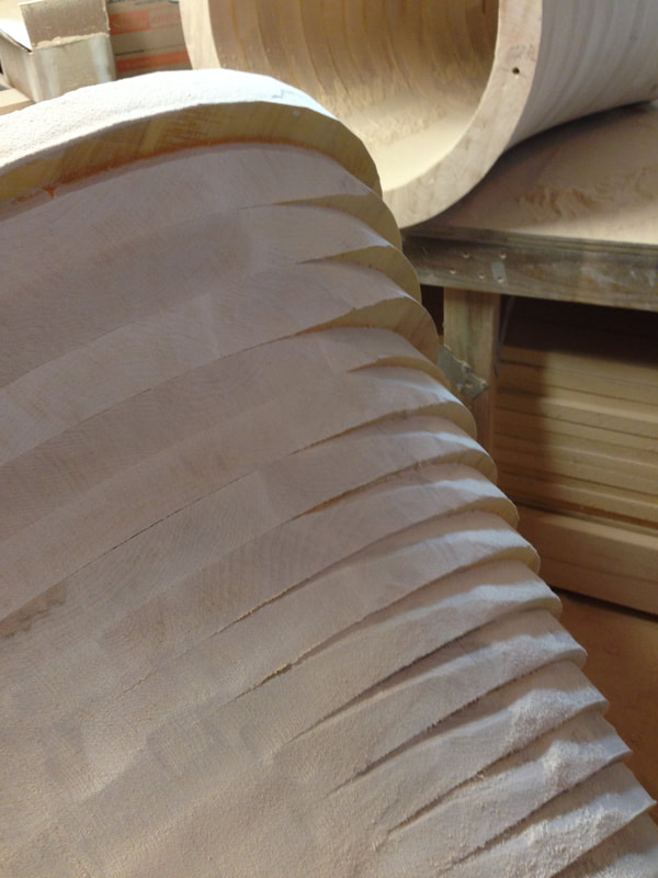
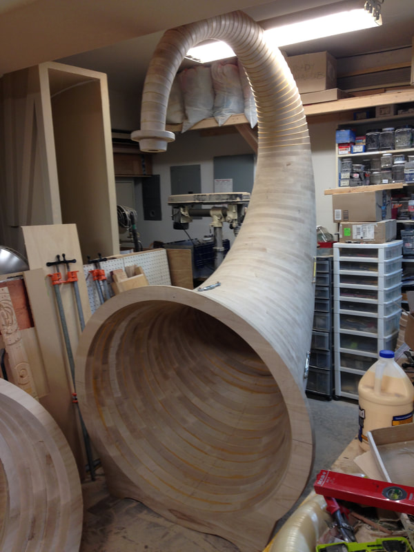
As you can see, there's a lot of planing/sanding in my future. I'll take a hand held, right angle grinder with a shaping disc
to rough in the high spots, then move on to a belt sander, after which comes the orbital sander.
to rough in the high spots, then move on to a belt sander, after which comes the orbital sander.
Shaping and sanding:
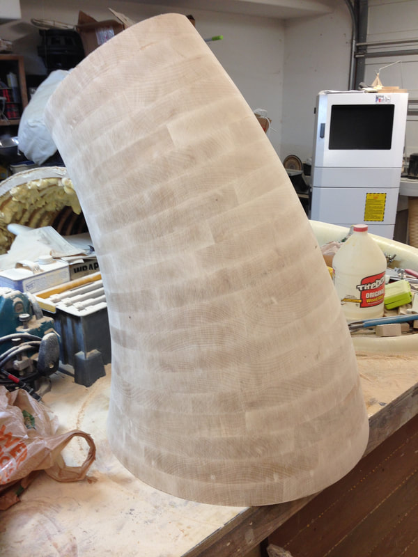
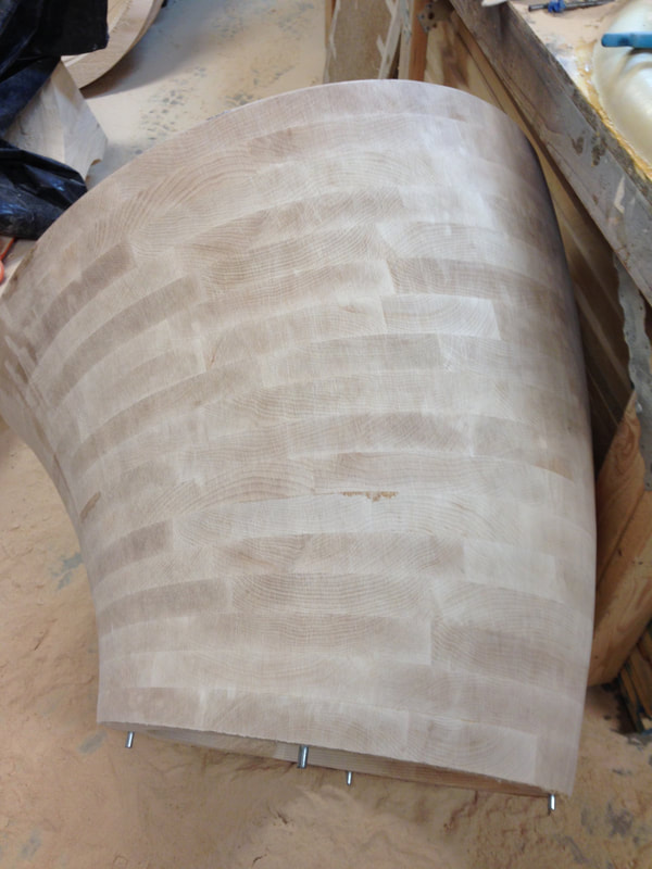
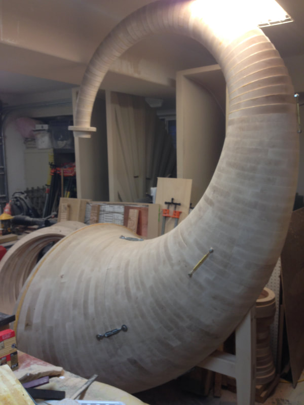
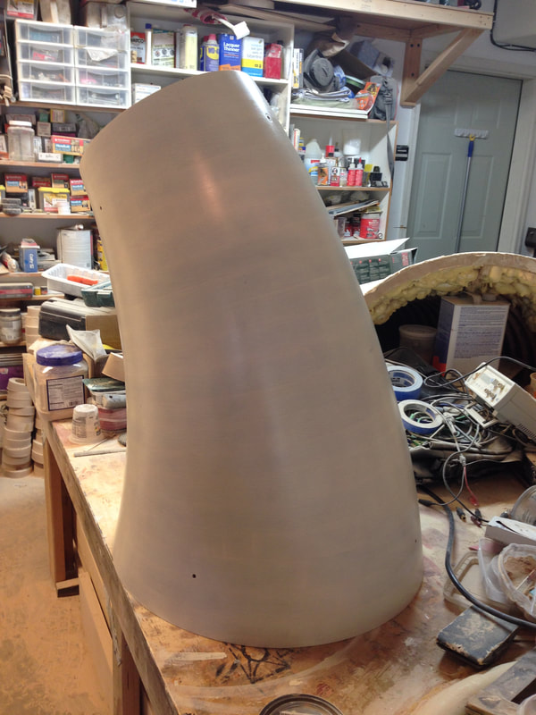
Below: I'm grinding off the unwanted material. It's a dirty, time consuming job--thank god for quality respirators! There are slight voids here and there that will be filled with maple imbued epoxy (fine particles of maple are added to the epoxy).
I won't lie, the labor involved in the shaping/sanding process is far more than the average project requires. I must have generated 30 lbs. of sawdust! I've completed the exterior rough in phase, and will move on to planing/aligning the horn's mating surfaces. Combined, the wood rings on the first two mouth segments are out of alignment by 1/4 inch, they don't mate uniformly, so I'll have to create a fixture to allow me to correct the situation.
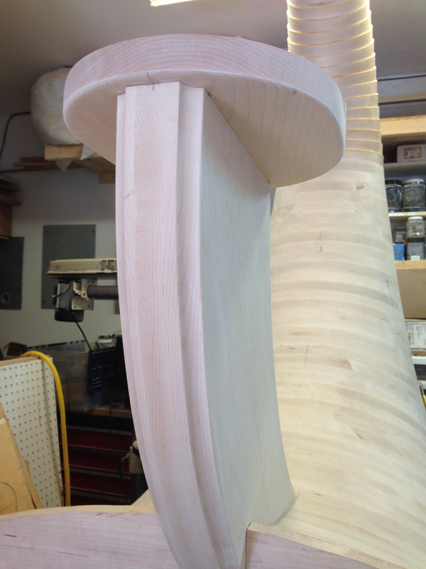
Below: I've created a dandy flange to couple the horn to my customer's compression drivers.
Below: I've created a dandy flange to couple the horn to my customer's compression drivers.
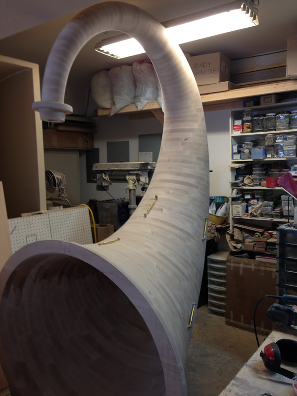
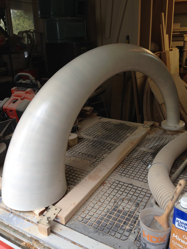
Below: Completed fabrication of the goose neck portion of the horn:
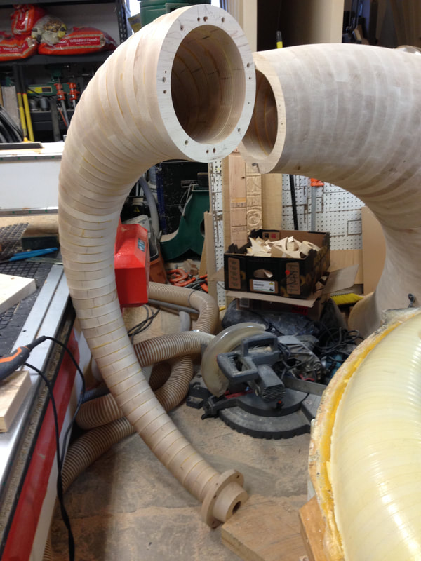
Yes, it's huge!
My shipment of attractive brass turnbuckles arrived the other day. They're much nicer looking than the Home Depot variety (Home Depot's are silver gray).
The horn requires a strong perch to support the drivers.
Below: the compression driver!
Below: Exterior sanded. Moving on to the interior.
Below: Staining the horn
Below: three coats of stain and five layers of urethane
|
|
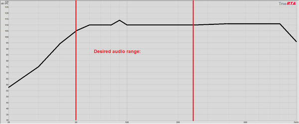
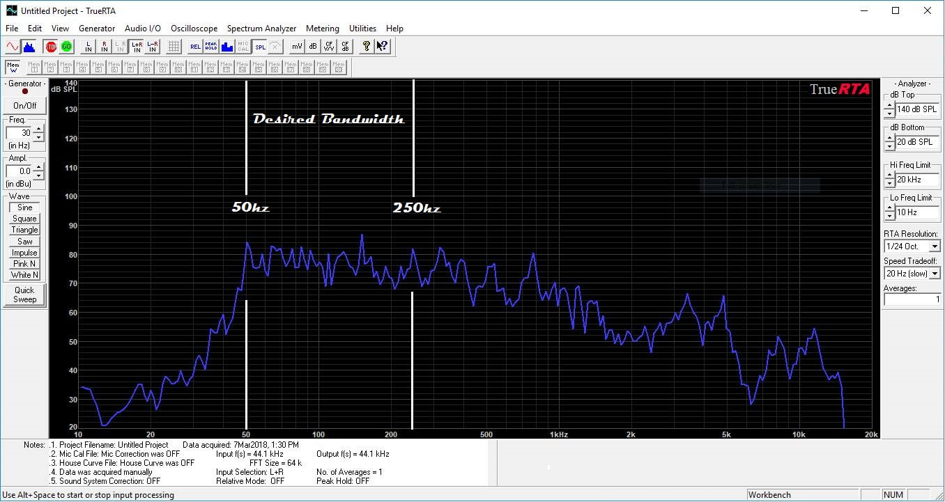
Below is the RTA performance graph taken with my 1 watt Darling amplifier. I used TrueRTA on my laptop, and I believe my laptop may not be capable of properly representing low frequency response; the internal sound card may not be up to snuff. Still, this gives a quick representation of the horn/driver bandwidth.
My iPhone's response when I used Bass Mechanic as the tone source (measured every decade):